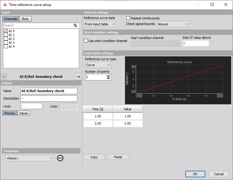
Time reference curve
Time based reference curve is useful for defining a curve in time as a reference during the certain test, which has to follow the certain protocol. The generated reference curve is compared with the channel selected as the input channel in the Time Reference curve setup.
Reference curve data
You can either define the values of the Reference curve manualy in the input table or you can choose a signal from a data file.
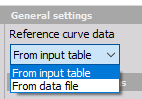
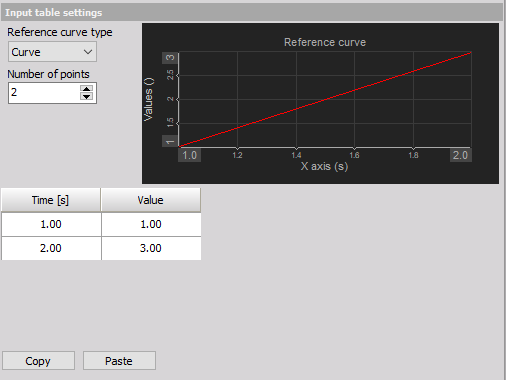
From input table We can choose between two different Reference curve type options.
If a Curve option is selected one reference curve is created.
If an Envelope type is selected two reference channels are created, which are meant as upper and lower limit.
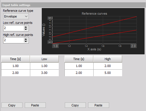
We select the Number of points we want to use to define the Time Reference cureve. Then we can enter the values manualy or copy them from an external software e.g. Excel with the “Copy” and “Paste” buttons. When the envelope type is selected, be sure that you insert lower values for the lower reference curve and higher values for the Higher Reference curve.
From Data file
When you choose the “From Data file” option the following settings will appear.
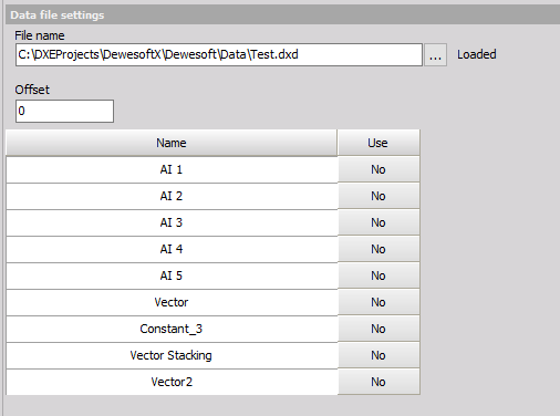
When we select the wanted data file all the possible channel will appear on the list. We can also adjust the Offset of the channel we want to use as our Reference channel.
Repeat continuosly
The Reference curve values can be Constantrly repeated if this option is enabled. This mean when the last value of the Reference curve is presented the Reference curve will not stop but rather continue from the first value on.
Reference boundry check channels
Additional channels are created to check the signal bounds conditions. We can choose from the drop-down list if we want to check the boundries always or only when storing the data.
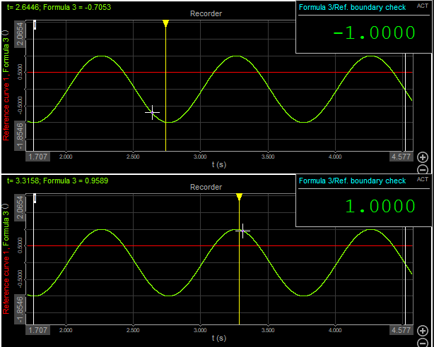
When the Curve type is selected the Additional channell value is defined as following: If the selected input channel exceeds the reference curve value, the additional channel will return a value of 1. If the selected input channel does not exceed the value, the additional channel will return a value -1. If the input channel has the exact value as the Reference channel the additional channel will return the value 0.
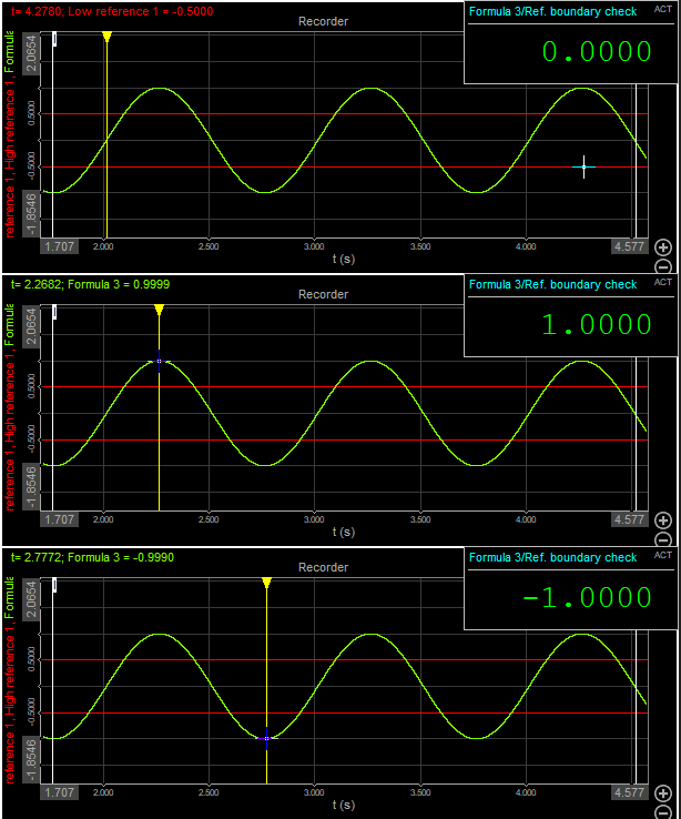
When the Envelope type is selected the Additional channell value is defined as following: If the selected input channel exceeds the upper Reference curve value, the additional channel will return a value of 1. If the selected input channel exceeds the Lowe Reference curve the additional channel will return a value -1. If the input channel is between the boundries the Additional channel will return the value 0.
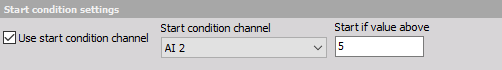
Start condition settings
In the following settings we can adjust the start conditons for the Reference curve. From the drop-down list you can select the channel that you want to use.