Time-to-vector transform
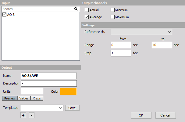
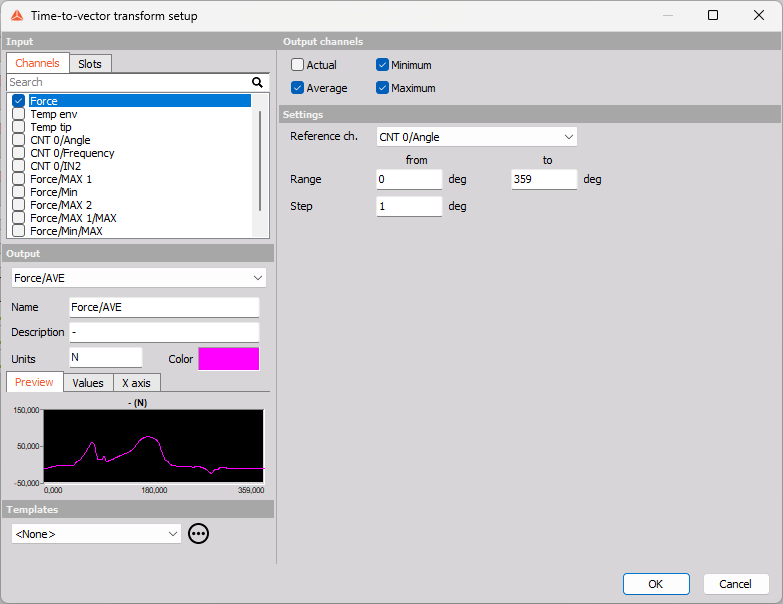
When you press the Setup button on newly activated Time-to-vector transform line, the following setup screen window will open:
With the Time-To-Vector transform function, each signal can be resampled from time-domain to the domain of another channel. It is very helpful when working on cyclic (reciprocating) machines like motors, compressors, production / stamping machines, etc.
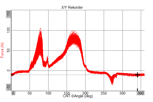
Example: On the raw data below you see a cyclic process, where 2 signals were acquired: - Angle sensor, e.g. Encoder-360 with high angle resolution (red) - Force sensor (blue)

Since the process repeats, it might be interesting to change from time-base to angle-base (angle-domain), having 0…360° on the x axis. Then the cycles can be overlayed.
The easiest way is using a X/Y recorder widget, and first selecting the Angle channel on the x axis, then the Force on the y axis. You will see all cycles overlayed, which you are looking at in the zoomed region of the data file.
With the Time-Vector-Transformation you can do more: statistical calculation like AVG, MIN, MAX, based on angle-domain. Just select the Force sensor as input channel, and the Angle channel as reference. The resolution on the resampling you can select, e.g. having a resolution of 1 deg.
Then use a 2D Graph and assign the newly created channels Force/AVE, Force/MIN and Force/MAX from the channel list on the right.
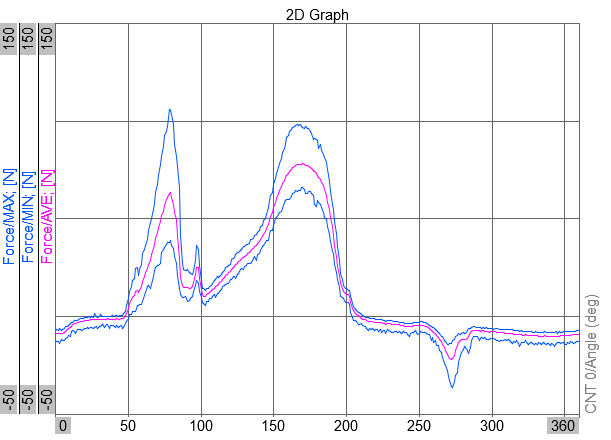
Hint: for further calculation you can use the Math -> Basic statistic -> start/stop-Blocks, and search with rising edge to rising edge the two local max values in the range from 50 to 100 deg, and 150 to 200 deg.
Please also check out the similar functionality with 2D/3D Mapping function.